
Flight simulators are essential tools used for training, entertainment, and research. They have evolved from simple models to highly sophisticated systems.
A flight simulator replicates an aircraft’s controls and environment, providing a virtual flying experience. Initially developed for pilot training, they now serve various purposes, including entertainment, research, and emergency procedure training. This article explores flight simulators, their purpose, and offers a guide on creating your own.
A flight simulator is a system that mimics the physics, controls, and behavior of an aircraft.
Flight simulators model an aircraft’s cockpit, instruments, and flying environment, allowing users to interact as if they were piloting a real aircraft.
- Full Flight Simulators (FFS): High-fidelity simulators used by professional pilots for training, featuring motion platforms, visual displays, and comprehensive controls.
- Fixed-Base Simulators (FBS): Used for training without the motion component.
- Desktop Simulators: Accessible on personal computers, popular among aviation enthusiasts for entertainment or casual training.
- Pilot Training: Primarily used for pilot training, helping pilots practice flying in various weather conditions, emergency scenarios, and complex airspace systems.
- Entertainment and Gaming: Popular in the gaming community, allowing users to experience the thrill of flying.
- Research and Development: Used by aircraft manufacturers and the aviation industry for testing aircraft designs, flight dynamics, and safety features.
- Public Education: Utilized in aviation museums and educational facilities to introduce people to the basics of flight.
This section outlines the key steps involved in creating a simple flight simulator, from planning to implementation.
Decide on the complexity of your simulator. Are you creating a basic 2D flight simulation or a full 3D simulation with advanced physics? Determine whether the simulator will focus on specific aircraft types, flight dynamics, or a broad range of general aviation aircraft.
- Programming Language: Most flight simulators are written using languages such as C++, Java, or Python due to their performance and flexibility.
- Graphics Engine: Use a graphics engine like Unity3D, Unreal Engine, or OpenGL for rendering 3D environments.
- Flight Simulation Libraries/Frameworks: Utilize open-source frameworks like FlightGear, X-Plane SDK, or SimConnect (for Microsoft Flight Simulator) to streamline the development process.
- Flight Dynamics: Accurate flight physics are crucial. Research aerodynamics principles to simulate lift, drag, thrust, and weight. Tools like OpenFlight and JSBSim can assist with this.
- Aircraft Models: Build or obtain detailed models of the aircraft you wish to simulate, including both the external shape and internal cockpit controls.
- Environment Modeling: Design the landscape, airports, runways, weather patterns, and time of day. Use elevation data for terrain and satellite imagery for realistic environments.
Design the cockpit with all necessary controls, displays, and instruments (e.g., altimeter, artificial horizon, speed indicator). This involves user interface (UI) programming and interaction design.
Program the flight controls, such as the yoke, throttle, pedals, and other input devices. Implement support for real-world flight control hardware (joysticks, yokes, and pedals). Use input handling libraries for keyboard, mouse, or controller inputs and link them to the simulator’s actions.
Test the simulator extensively, focusing on fine-tuning the user experience, flight physics, and overall performance. Identify and fix bugs, glitches, or unrealistic behavior. Ensure the simulator performs well on various devices.
- Realism: Strive for realism in flight dynamics, aircraft systems, and scenery. Implement features like realistic weather conditions, autopilot systems, and engine performance.
- Multiplayer and Networking: Add networking capabilities for users to fly together in a shared virtual environment. Implement multiplayer functionality and data synchronization for real-time interaction.
- VR and Motion Sensing: Integrate VR compatibility for an immersive experience. Motion-sensing devices can simulate the physical experience of flying, adding realism.
Flight simulators are powerful tools that have transformed pilot training, aircraft development, and aviation engagement. Whether for professional use, entertainment, or research, building a flight simulator is a rewarding challenge. With the right tools, dedication, and understanding of flight dynamics, a nyone can start developing their own simulator. As technology evolves, the possibilities for flight simulation are limitless.
This structure provides a clear flow for your article, starting with an introduction to flight simulators, followed by a step-by-step guide on creating one, and finishing with a discussion of advanced features. Adjust the details according to your audience, whether they are beginners or experienced programmers!
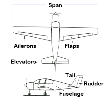
Fuselage: The body of the airplane
Wings: The generally flat structures that generate the lift which make the airplane fly
Tail: The back of the airplane which consists of a vertical and a horizontal section. Its main role is to stabilize the airplane.
Ailerons: Movable areas on the outer part of the wings, used to make the airplane roll.
Flaps: Movable areas at the inner part of the wings, used to increase lift at low speeds and drag.
Elevators: Movable areas of the horizontal tail section used to control pitch.
Rudder: Movable area of the vertical tail
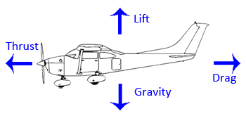
The primary force acting on any object is gravity. To achieve flight, we need to generate an equal and opposite force known as lift, which is produced by the wings as the airplane moves forward. This movement is driven by thrust, and due to aerodynamic resistance, we encounter a force opposing the movement called drag. Gravity is the existing force, while thrust is the force controlled by humans. Lift and drag are the outcomes of the airplane's movement.
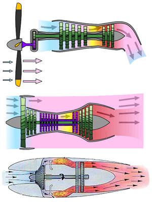
We begin our journey with the primary force we generate on the airplane: thrust. Thrust is the energy source that airplanes need to create lift and ultimately achieve flight. Gravity, one of the fundamental forces of nature, is always present. However, to generate lift, we must make the airplane move, and thrust accomplishes this.
So, what exactly is thrust and where does it come from?
Thrust is the force produced by the engine that propels the airplane forward. There are various methods to convert the mechanical energy generated by the engine into thrust. The oldest method involves a propeller attached to the engine's drive shaft, while the most modern method uses jet engines.
In the image, we can see the three basic types of thrust generators designed for larger airplanes that require more power. For smaller airplanes, the propeller is powered by smaller reciprocating engines instead of turbines.
The first type of engine is the turboprop, the second is the turbofan, and the third is the jet engine. Delving into the working details of these engines is beyond the scope of this article.
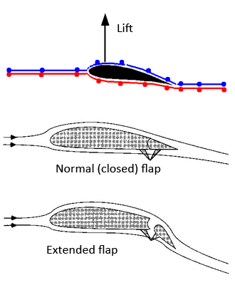
We understand that lift is a result of the airplane's movement due to thrust. Let's delve deeper into what happens when the airplane moves.
Any object moving within a fluid, such as air, generates two forces. One force, called drag, opposes the direction of movement and is proportional to the object's size, shape, the fluid's viscosity, and the square of the object's speed. The other force, perpendicular to drag, is known as lift. The magnitude and direction of lift are determined by the shape and orientation of the airplane's main surfaces, primarily its wings. A poorly designed airplane might generate negative lift, which is desirable in sports cars.
How is lift generated? The wings' shape causes the air above the wing to move faster than the air below it, creating a pressure difference that results in lift. Another crucial factor is the "angle of attack," which is the angle between the wing's longitudinal axis and the airplane's direction.
However, things are not so simple. Modifying the wing's shape to generate more lift also increases drag. If the angle of attack is increased too much, the airflow over the wing becomes turbulent and detaches, raising pressure and reducing lift.
Therefore, we need a mechanism to alter the wing's shape and generate significant lift at low speeds for quick takeoff and slow-speed landing approaches. This mechanism is the flaps. The flaps extend and move downward based on the pilot's decision. Extending the wings in this manner generates the necessary lift at low speeds to keep the aircraft airborne. As airspeed increases, the pilot retracts the flaps since the wing can generate the required lift without additional assistance.
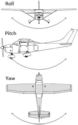
To navigate the airplane to the desired location, the pilot uses the controls to perform one of three movements shown in the image.
Roll: This is the rotation around the airplane's lengthwise axis (from nose to tail). It's controlled by the ailerons, which are small flaps on the wings. When one aileron goes up and the other goes down, the airplane rolls to the side.
Pitch: This is the rotation around the airplane's side-to-side axis (from wingtip to wingtip). It's controlled by the elevators, which are flaps on the tail. When the elevators go up, the nose of the airplane goes up, and when they go down, the nose goes down.
Yaw: This is the rotation around the airplane's vertical axis (from top to bottom). It's controlled by the rudder, which is a flap on the tail. When the rudder moves left or right, the nose of the airplane turns in that direction.
Combining these movements allows the pilot to steer the airplane in different directions.
How does the airplane respond to these movements? To understand this, we need to analyze how the control surfaces influence the airplane and cause it to move. When a control surface like an aileron moves, it diverts the airflow around it, creating a force. These forces generate torques around axes that pass through the airplane's center of gravity. Summing up all these torques gives us the final torque that changes the airplane's orientation.
We can assume that the airplane itself is a rigid body. Although we have seen airplane wings vibrating during flights, indicating they are not entirely rigid, we can ignore this for our simulator. Therefore, we only need to know the airplane's total inertia, which is the sum of the local inertia of its elements, such as the fuselage, wings, flaps, ailerons, and rudder.
Delving into the physics model of a flight simulator is beyond the scope of this article. My aim is to provide a simple overview of what is involved in creating the simulator. The airplane's physics model was originally developed by David M. Bourg in his book "Physics for Game Developers" (ISBN: 0-596-00006-5 © O'REILLY 2002). This book is an excellent resource for understanding game physics. The beauty of physics is that it remains relevant over time, so if you can find a copy, I highly recommend reading it.

The simple simulator we created divides the screen into two areas. The top section displays the view from the pilot's window, while the bottom section is the instrument panel. The instrument panel consists of a map of the world with the airplane always centered and pointing upwards. This view is essentially the same as the top view but from a different perspective. On the left side, you will see five instruments: the artificial horizon, the roll indicator, the compass, the altitude-speed-climb rate indicator and the throttle and stick position.
The stick that controls the ailerons and elevators is operated by the mouse. Moving the mouse up or down operates the elevators, while moving it right or left operates the ailerons. The throttle is controlled by the 'A' and 'Z' keys. The simulator is quite simple, and the scenery is not very detailed. There is no takeoff or landing procedure, and the action starts in the air. No collision detection is performed, and the earth is flat and limited. The visual effects developed in previous articles are included, and the airplane physics are modeled effectively.
In this sample we make extensive use of all the thins we discussed so far. We have multiple views and cameras, we perform scissor tests to limit the extension of our drawing and so on.
In this part we saw some elements of a real-world game/simulation application where we used most of the techniques we developed so far.